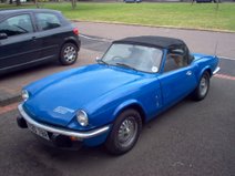
Saturday, September 18, 2010

Headlight Relays

I wrote this blog entry a month or so ago but I was so busy preparing for the Round Britain Reliability Run I never got a chance to post it. So, finally, here it is...

I've had a couple of problems in the past few days with the dip / flash stalk on the steering column. My uprated Halogen headlamps seem to have been putting much more strain on the switchgear than the old sealed beam units. Last year I had to take the stalk off and repair it because the full beam terminal seemed to have heated up and melted into the nylon body of the stalk causing it to smoke and spark quite dramatically! After it failed again on the same dark country road as before I decided it was probably time to fit some headlight relays!

I'm not the greatest electrical engineer in the world so I decided to do my research first. After a bit of searching I found an excellent thread on the Club Triumph forum. Once I understood what I was doing I made up a circuit diagram.

Basically, instead of going direct to the lights the wires from the switchgear go to a relay instead. When the light switch is pressed the relay circuit activates the secondary circuit which connects the lights directly to the battery. So that's the theory! You also need to do a bit of maths to make sure the cable can support the current it needs to be carrying. All you really need to know is Power = Current x Voltage. Most headlamp bulbs are 55/60 Watt so the current will be around 5 amps. Because there are 2 headlamps we need cable and relays that can take at least 10 amps. I decided to go a bit bigger on the battery supply cable to give me more capacity for upgrades in the future. The relays required are the common as muck 30A type.

I first thought about where I was going to mount the relays themselves. It's easiest if they're up front with the rest of the wiring for the lights. On the CT forum, James mentioned that he'd seen the relays P clipped to the bonnet tubes. Initially I thought this would be a great idea but when I looked into it a bit more I discounted it on the grounds that the cables would eventually get weakened by the movement of repeatedly opening the bonnet. I decided on a custon bracket bolted behind the quater valance. I made this up out of 3mm alloy and test fitted it. Perfect! Now to start the wiring...


I started by fitting the brown relay supply cable. This attaches to the battery positive terminal with a ring terminal and goes straight to an inline fuse holder before joining the rest of the loom running to the front of the car.


At the front of the car I crimped it into a butt connector along with another two short lenghts to supply both of the relays. The brown wire attaches to the '30' terminal on the relay. On the picture below you can see a left over length of the brown wire is being used to temporarily hold the relays in place!


You can then start attaching the other wires. The low and high beam cables can be found by tracing the cabling from the headlamps to the connectors in the centre of the bonnet. There should be a number of 4-way connectors, each with 3 wires connected to it. The low beam is the blue wire with a pink trace. Remove the supply wire from the connector (the others go to the headlamps), shorten it, crimp a terminal and attach it to the relay. Now you just need to repeat that with the high beam wire (blue with white trace) and connect it to the other relay.


All you then need to do is connect up both the '87' terminals on each relay to the connectors by the headlamps. There we go - all done!

Wednesday, September 01, 2010

Electronic Ignition

I've been meaning to change to electronic ignition for ages. I was hoping to go straight to Megajolt but with the RBRR coming up fast I decided it was time to get something sorted! I've heard good things about the kits sold by 'SimonBBC' so I got one of eBay. BBC stands for 'Best British Classics' in case you're wondering and they have a website (http://www.simonbbc.com) as well as selling on eBay.

The kit contains a red module to put in the distributor, special rotor arm, a magnetic 'collar', grease, cable tie and various other bits. The fitting goes a little like this...

Firstly, you need to whip off the distributor cap to expose its innards. You no longer need the condenser or the points so they can both be removed by removing the two screws. You need to reuse the screws so keep them safe! There is also a braid connecting the baseplate to the distributor body. It doesn't say anything in the instructions about it but I removed it and it worked so I guess it either needs to be removed or makes no difference!


Once you've stripped the guts out you can install the ignition module. This needs to have the base coated in silicon grease before fitting. I think the reasoning behind this is to dissipate heat into the baseplate and prevent overheating. The module has a circle cut out of the bottom that matches up with a lump on the baseplate so the module 'locates' very easily. The instructions tell you to put the screws in loosely so you can adjust the proximity of the module to the collar on the distributor shaft. I actually found that with the locating bump and the two screws there wasn't really any potential for moving it and just did up the screws.


Now you need to fit the rotor arm and collar. The kit gives you a couple of different ways of doing this. Firstly, you can use the supplied rotor arm which comes with a collar built into the bottom to activate the ignition module or, secondly, you can fit a separate collar and use your own rotor arm. I'd just bought a new top quality 'red' rotor arm so I went with the latter option.


Then all you need to do it pass the wires out through the distributor body and connect the red one to the plus side of the coil and the black one to the negative. It's really important to leave enough free cable inside the distributor to allow the plate to advance and retard. I checked mine by sucking on the vacuum pipe! The cables in the kit were a little strange. One was too long and the other too short! I sorted this with a little spare cable and a few crimp connectors.

I then threw it all back together and reconnected the battery. It was time for a test drive! I turned the key and the engine span over but nothing happened. Something was wrong and it wouldn't fire. I suspected my connections at first but everything seemed to be in order when I tested them with my multimeter. There isn't much in this kit that can actually go wrong so my suspicions turned towards the stuff in the diff! I fitted the rotor arm with the built in collar just to see if that made any difference and it did! The engine fired up straight away. Comparing the position of the collar on the rotor arm with it built in and where I had it with my normal rotor arm revealed the problem. Basically, I'd just pushed the collar too far down the shaft for its motion to be picked up by the ignition module. All I did was refit the normal rotor arm and pull the collar up to the bottom of it. Job done!

I haven't driven the car since doing it but just at idle it sounds much smoother and I'm sure it's going to make a huge difference to how the engine feels. I'm really glad I did it and I can't believe I didn't do it sooner!

Sunday, August 15, 2010

Wiper Issues and Power Socket

As anyone who rebuilds cars will tell you - sometimes things go well and sometimes they don't! I've had a number of things that haven't worked out recently. Firstly, the baffled sump I nearly finished had to be abandoned because it had issues with the screen touching the crank. Then there were issues with the trim I bought for the bottom of the hardtop which I managed to cock up fitting. It looked like a horrific water trap too so I ended up ripping most of it off! To top it all off, I found a puddle of water in the passenger footwell!

It was pretty easy to find the source of the water leak. The passenger side windscreen wiper mount was loose and the rubber seal was missing, allowing the recent 'summer weather' to pour in! The wiper and nut came off pretty easily but the chromed pedestal needed a bit of leverage from a screwdriver. I made a new seal from a sheet of silicone.

The old seal on the drivers side was literally dust and no use as a pattern so I drew around one of the spindles to make a pattern.


The only hitch was refitting the passenger side nut. The reason the whole thing was loose in the first place was because someone had overtightened the nut and ruined the thread. Unfortunately the thread looked pretty unusual and, as I'd got no idea what it was, there was no option other than to buy a new wheelbox. Hopefully that'll arrive soon!

Over the weekend I also installed a power socket. It's fitted to a metal bracket on the passenger side of the dash. I originally built the bracket for an extinguisher pull handle but never got around to fitting a plumbed in fire extinguisher! With the help of a conical drill bit set from Machine Mart I enlarged the hole enough to take a VW power socket I bought from eBay. I originally finished the bracket by polishing it but this time I sprayed it using wrinkle finish paint. Wiring was simply a case of hooking it up to a purple wire in the 'always on' circuit that I picked up from the hazards relay and earthing the other terminal. Done!

Saturday, July 17, 2010

Progress Update!

Things have really started coming together over the last few weeks. I've got the back of the engine sorted and the gearbox back in. I chucked in a lightened flywheel I bought of Martin Holmes on the Sideways forum, ARP bolts and a new clutch from Canleys. Everything went quite smoothly apart from a few minor niggles. The first problem was that the holes in the clutch cover for the flywheel dowels were ever so slightly too small and needed drilling out by half a mm. The second problem I had was that the hole in the alloy bellhousing for the engine dowel was clogged up with POR15 and also needed drilling out.

I also took the time to replace the clumsy old exhaust clamps with Mikalor band clamps.
I decided to make a better effort at sealing the gear tunnel and renewed all the fixings, replaced the sealing foam and also made an aluminium cover for the slave cylinder inspection panel.
I shampooed and rinsed the carpets. They're in dreadful condition really and they seem to have been made by someone that has never even seen a Spitfire before but they'll do for now!

I also repainted the gear pattern on the gearknob before I refitted it. It looks good! I'm just waiting on the leather seat covers now!

Monday, July 05, 2010

Sat Nav

In October I'm taking part in Club Triumph's Round Britain Reliability Run. Obviously, this involves having a fully working car and I'm working on it! It also involves doing a lot of driving and navigating! On the Historic Counties Run, one of the most annoying aspects was the Sat Nav. We used a Garmin model with out of date maps and we couldn't plug it in because the car doesn't even have a lighter socket!

This got me thinking about possible navigation solutions. I work in IT and figured that there must be a PC based solution I could use. I've got a tiny Dell 'netbook' and I figured that I could use that with a GPS 'dongle'. I thought it might also allow me to track the car and overlay the track over Google Earth and also maybe allow me to attach a webcam and make a time lapse video. The netbook solution also has the advantage of being very cheap - I already have a netbook, GPS dongles are around £30 and you can download a fully featured time limited demo version of Microsoft Autoroute for free.

So far I've tried navigating using the netbook in my VW and it's been great. Not quite as easy out of the box as the Garmin but the tracking works well and the spoken instructions are better because Autoroute actually says the road names. It also seems to have better lane guidance. It is a bit quirky in some ways, though! It took me ages to convince it not to navigate me back to a missed waypoint. I must find some more time to get used to it!

Sunday, June 13, 2010

Sump Baffling

It's always surprised me that you can't buy a baffled sump off the peg. It's also surprisingly difficult to find info about the best way to baffle a Spitfire sump. A lot of the 'tuning know how' books tell you that you need one but all of them seem to fall down when it comes to providing specific details...
Luckily the Internet provided a few answers with threads on the Club Triumph and Sideways Technologies forums providing some good nuggets of information from those that have done this before.
For me, the first thing to do was to get a spare sump from EBay. When this arrived I was surprised to see it came with a mesh screen over the deep part of the sump. After asking around I discovered that the early models were fitted with mesh like this to stop bits of metal being ingested by the oil pump. Later models have an oil strainer attached directly to the pump.
I decided to keep this mesh screen - a lot of aftermarket windage trays use a similar arrangement. This meant modifying it to fit my fatter (later) oil pump. I drilled a series of holes and used a small chisel knock out the metal I didn't need. This worked surprisingly well and the finished result, after filing, is very neat.
Next it was time to make a cardboard template. I decided to go for a flat plate to control front / rear movement, with a vertical piece running from front to back to control sideways movement. When I was happy with the templates I transferred the design to aluminium.
With the flat plate made up in alloy I realised I was going to have a problem getting it past the windage tray! I solved this by cutting it in two and drilling both halves for rivets. I then made the vertical baffle from a piece of L shaped alloy and drilled it so I could attach it to the horizontal plate - using it to neatly combine the two halves!
I then started thinking about how I should attach it to the sump. I didn't like the idea of bolts through the side of the sump so I decided to make some C shaped brackets and attach it to the windage tray. I decided to use rivets at the bottom and cap head bolts at the top. With the baffle now able to be attached, I riveted it up so I could test the baffle with a sump full of water.
It seemed to be pretty effective so I'm pretty happy with the design. All I need to do now is add the holes in the baffle for the oil pump and the dipstick and I'm done!

Wednesday, May 12, 2010

Helicoils How To... (And How Not To!)

I got home today to find my Helicoil kit waiting on the doorstep. I threaded the alloy rear oil seal housing at the weekend and decided it'd be a better idea to repair it rather than buy a new one and risk threading that too! It's cost efficient too, a new housing would've been £20 whereas the Helicoil kit was £15! I got my kit from Chronos Engineering because they sell kits that contain everything you need so you don't have to spend ages searching for obscure size drill bits.

The kits are specific to a certain bolt size and contain around 25 Helicoils, a drill bit, a tap, an allen key, an insertion tool and a small drift all in a nice blue case!

So here's the problem. Basically a classic case of Triumph using the wrong fastener in the wrong place. The alloy is really very soft and it would have been better if Triumph had used a UNC thread like they did on some other alloy parts such as the intake manifold. Instead they used a UNF thread on both this and on the engine front sealing block.

First thing to do was to drill the threads out. I checked the depth of the holes and wrapped a bit of tape round the drill bit from the kit so I didn't go too deep! The alloy was very soft and drilled nice and easily.

The next stage of the process is to thread the hole for the Helicoil insert. The kit comes with the tap but you'll need a tap wrench if you haven't already got one. I borrowed a tap holder from my Clarke Imperial tap and die kit and that worked a treat. With tapping it's always best to take it slow and keep the tap well oiled but when the metal is as soft as this, you can go pretty rapidly!

Once the hole is tapped to the bottom you can remove the tap and run it through a few times. I cleaned the swarf out with light oil from an aerosol to clear it.

Inserting the Helicoil is very straightforward. It's basically a spiral of metal that has a small 'tang' sticking into the middle at the bottom. To fit it you use an insertion tool that is basically a drift with a slot in the end which engages with the tang on the Helicoil. The one in my kit has a depth stop so you can sink the coil down to a set depth. This is secured using a grub screw and the allen key from the kit.

With the Helicoil in place, all you need to do is knock the tang off. The tang is weakened and should knock off pretty easily using the drift from the kit.

This worked well for me on one of the holes but not on the other! On the one hole the drift didn't seem to knock the tang of very cleanly. The last thread ended up sticking out slightly and when I screwed in a bolt it seemed to push the thread down underneath the bolt. This meant that the bolt wouldn't screw fully home and left the Helicoil in a right mess! I had to get it out!

I thought this would be near impossible but it was actually fairly straightforward. You've just got to bend out the top thread until you can get a pair of pliers on it and then the whole thing will unscrew just as easily as it went in. Once the mangled Helicoil was out, I cleaned up the threads again and fitted a new Helicoil. This time I snapped the tang off by gently wiggling the insertion tool forwards and backwards. This worked a treat and after running the Helicoil through with a tap I was happy that the job was done!

Sunday, May 09, 2010

Clutch Stuff

I might as well rename my blog 'Will's POR15 blog'! I've been using huge amounts of the stuff over the last month! Firstly there was my alloy bellhousing which I painted inside and out, then there was the clutch release lever and then finally the gearbox casing which I painted up to match. The grey doesn't seem to go on quite as well as the black but the finish is very good all the same.


Once the bellhousing was painted I refitted the steel insert that the release bearing carrier slides on. After doing this I realised that something wasn't quite right. Canley Classics website describes the insert as 'Part 122566 - Bellhousing Centre Her/Spit (Scroll Type)' but when I took it off there wasn't any kind of oil seal on there! Fortunately the situation was easy to solve with a later type bellhousing centre that takes an oil seal.

While I was there I thought I'd renew the slave cylinder pushrod and the pin that holds it in the release arm. Incredibly, there was more than 2mm of wear in these two parts! The new pushrod was a bit fat and needed the attention of a bench grinder but was otherwise easy to fit. Once I'd done that I tried to fit the release lever into the bellhousing and ran into another problem!

Basically, the clutch release lever just wouldn't move smoothly over the bellhousing centre. This seemed to be due to the inside of the bellhousing being slightly cast wrongly. I have to say that the general quality of the alloy bellhousing is pretty poor and I suspected when I first saw it that it might need some 'altering'. In the end though, I decided to just grind a bit off the bottom of the release arm instead. This gave the necessary clearance and the throwout sleeve on the arm now slides smoothly like it should!

While I was in a painting frame of mind I painted the engine back plate and the drivers side floor in POR15. The drivers side floor is a mess and has a couple of plates welded on and a few tiny holes. I'm aiming to replace this in the near future but for the time being I just want to stop it getting worse so painting is the answer!

I did actually buy an alloy engine backplate but I don't think I'm going to use it. I've heard tales of the alloy ones cracking around the bottom bolt holes and I sure as hell can't be bothered to sort that out in the future so I'll be sticking with steel!


I've had one slight hitch with the engine this week. I was just fitting the renewed rear oil seal to the back of the sump when I stripped the threads in the alloy housing. This was a right pain because my brother came to visit this weekend and I had hoped to have the gearbox and engine ready to go back together. It'll have to wait now until I've helicoiled the threads. I've not done this before but it looks straightforward enough. I've ordered a kit from the eBay shop of Chronos Engineering. Hopefully that'll arrive in the week and I'll be back on track next weekend!

Friday, March 26, 2010

Gearbox out!

This week has been a busy one! I started the week by fitting one of those 'Stant' lever radiator caps. This is straightforward enough but, if you're thinking of fitting one, you need to get a few things right. Firstly, the pressure rating has to be right (13lbs) and, secondly, it has to fit under the bonnet! I checked this very carefully before dropping the bonnet down for the first time!

The next job was a big one! The gearbox needed to come out so I could replace the engine's rear oil seal. I won't bore you to death with the details of how I got the gearbox out but it did involve a hell of a lot of brute force, wood and jacks. Believe it or not, I did it all on my own too!

The oil leak had made one hell of a mess. The inside of the bellhousing, bottom of the gearbox and the underside of the car were absolutely caked in oil and dirt!

The standard cast iron bellhousing weighs nearly as much as a chest freezer! I bought an alloy replacement from Moss last year and started preparing it to fit. It's not the best casting I've ever seen but I think it'll do. I've painted it inside and out and I've gone for grey POR15 this time to show up any oil leaks! It's a very similar colour to my workshop floor!

The seats are looking good. I've bought another seat foam set from Owen at Park Lane Classics. I haven't had time to do any more work on them though. I'm waiting till the gearbox is out of the way and my workshop is less dirty before I start work on them again!

Thursday, March 11, 2010

Progress In The Last 6 Days...

I've been working far too hard at work this year! I can't carry more that 5 days over to the next financial year so I've had to take four days off this week! It's been nice spending some time on the car and I've got a good number of the little jobs done.

On Saturday I had 'fun' with the water pump. I fitted this last week but I thought I'd better tighten up the nuts properly. You can't get a socket on these because of the pulley so I used one of my ratchet spanners. This was going well right up until I did up the last nut. I felt the nut tighten and then suddenly slip. I was gutted! My first thought was that I'd stripped the thread in the alloy water pump housing. Fortunately, I was lucky and it was just the stud! I couldn't get the stud off in situ so I had to remove the water pump.

I got a new stud in and made myself a new gasket. If you've never made a gasket you should try it! It's really easy and it saves loads of time. You can use card from a cornflake packet if you're desperate but the pukka stuff, which I use, is 'Flexoid' paper. It's really cheap on eBay and it can really get you out of a jam! All you need to do is trace around an existing gasket or place the paper over the flange and rub it over with a dirty finger to highlight the edges and then cut it out. You can make the holes by hammering a bolt into the paper. Easy!


Anyway, once I'd smeared a bit of Loctite 5926 gasket sealant on the faces I started bolting the water pump back in. This was all going well right up to the point where something threaded again! I couldn't believe it! This time it was the nut! I got a replacement and gave that a go. This time the stud threaded!

Something was definitely going on here! Once I looked into it, it was obvious what the problem was - the studs were too short! There weren't enough threads of the stud in the nut to take the torque of tightening. Once I'd realised that (and made another new gasket and found some longer studs) I was back in business. Sorted!

On Sunday I went to Stoneleigh. It was a brief visit again for me this year but I saw a few familiar faces and met a few new ones. There was loads of stuff for sale and I saw quite a few bargains. I really, really, wanted the mint bonnet that was for sale at £180 but I just couldn't have got it home in the back of my Golf! Instead I settled for picking up a few useful nuts and bolts!

On Monday I got my Nippon Denso alternator fitted. I'm still figuring out how the hell I'm going to wire this up but at least it's physically fitted in the car. I used a Canleys fitting kit. It was good but I'm going to replace the adjusting plate with a couple of rod ends in the near future.


On Tuesday I spent the day fixing the brakes on my Golf. The pads had seriously worn down with all the miles I'd been doing for work. In one case the friction material was down to 1.38mm! I decided to replace both the discs and pads as the discs had a massive groove around the edge because they seemed to be slightly oversize. I ordered replacement parts from Euro Car Parts and set about doing the job. It was all going swimmingly until I realised that the drivers side caliper wasn't sliding properly. Unfortunately the metal sleeve that the caliper slides on was seized solid on the caliper bolt and I had to destroy it to separate the two. Amazingly, my local VW dealers had the part in stock and I managed to get it back together on Wednesday morning!


On Wednesday afternoon I decided to finish off my anti roll bar links. I made my own out of rod ends from McGills Motorsport. There was a bit of work needed to get them fitted. I needed to drill out a sleeve to make a spacer and source some longer bolts for the wishbone end. Drilling out the sleeves was easy thanks to an 11mm cobalt drill bit from Namrick! Sourcing the longer bolts was tricky though. I couldn't find any online and eventually I had to get out the Yellow Pages. This worked out nicely and I turned some up at Nutters Fastenings in Nechells, Birmingham, which is just a few miles from where I work.


This morning I got another nice new part in the post. This time it was an alloy pulley from Rimmers. I'd heard bad things about alloy pulleys in the past. Apparently they used to be all alloy, which resulted in the keyway wearing out because of the softer material. The Rimmers one has a steel sleeve in the middle bolted to an alloy outer. Another bonus is that the bolts look like they might be handy for mounting a timing wheel if I ever want to move to a Megajolt set up in the future!