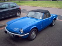
I've had a couple of problems in the past few days with the dip / flash stalk on the steering column. My uprated Halogen headlamps seem to have been putting much more strain on the switchgear than the old sealed beam units. Last year I had to take the stalk off and repair it because the full beam terminal seemed to have heated up and melted into the nylon body of the stalk causing it to smoke and spark quite dramatically! After it failed again on the same dark country road as before I decided it was probably time to fit some headlight relays!
I'm not the greatest electrical engineer in the world so I decided to do my research first. After a bit of searching I found an excellent thread on the Club Triumph forum. Once I understood what I was doing I made up a circuit diagram.
 Basically, instead of going direct to the lights the wires from the switchgear go to a relay instead. When the light switch is pressed the relay circuit activates the secondary circuit which connects the lights directly to the battery. So that's the theory! You also need to do a bit of maths to make sure the cable can support the current it needs to be carrying. All you really need to know is Power = Current x Voltage. Most headlamp bulbs are 55/60 Watt so the current will be around 5 amps. Because there are 2 headlamps we need cable and relays that can take at least 10 amps. I decided to go a bit bigger on the battery supply cable to give me more capacity for upgrades in the future. The relays required are the common as muck 30A type.
I first thought about where I was going to mount the relays themselves. It's easiest if they're up front with the rest of the wiring for the lights. On the CT forum, James mentioned that he'd seen the relays P clipped to the bonnet tubes. Initially I thought this would be a great idea but when I looked into it a bit more I discounted it on the grounds that the cables would eventually get weakened by the movement of repeatedly opening the bonnet. I decided on a custon bracket bolted behind the quater valance. I made this up out of 3mm alloy and test fitted it. Perfect! Now to start the wiring...

I started by fitting the brown relay supply cable. This attaches to the battery positive terminal with a ring terminal and goes straight to an inline fuse holder before joining the rest of the loom running to the front of the car.

At the front of the car I crimped it into a butt connector along with another two short lenghts to supply both of the relays. The brown wire attaches to the '30' terminal on the relay. On the picture below you can see a left over length of the brown wire is being used to temporarily hold the relays in place!

You can then start attaching the other wires. The low and high beam cables can be found by tracing the cabling from the headlamps to the connectors in the centre of the bonnet. There should be a number of 4-way connectors, each with 3 wires connected to it. The low beam is the blue wire with a pink trace. Remove the supply wire from the connector (the others go to the headlamps), shorten it, crimp a terminal and attach it to the relay. Now you just need to repeat that with the high beam wire (blue with white trace) and connect it to the other relay.

All you then need to do is connect up both the '87' terminals on each relay to the connectors by the headlamps. There we go - all done!


