Thursday, December 30, 2010

Safety First!

I've been thinking a bit about workshop safety recently. It all started about the time I bought my new welder. As I hinted in a previous post, I thought it was about time I started learning to MIG weld, so I treated myself to a Clarke 160TM from the Weldequip shop at www.mig-welding.co.uk.

Obviously, being new to MIG welding, I had to invest in the appropriate safety gear. There's a really good forum attached to the Mig welding website and virtually everyone on it recommended the auto dimming type of mask. I picked up a 'SIF Lite' mask off eBay for a very reasonable £45. This dims automatically when you look at bright light and should be just the job! In terms of clothing, I picked up a 'Silverline' apron (£6.89) on eBay and a pair of ESAB MIG gauntlets (£7.85) from the Weldequip shop.

My shopping list would have stopped there - but one of the guys on the Sideways Forum mentioned the importance of having a fire extinguisher. This got me thinking! Obviously, I've always had a workshop fire extinguisher but had I ever really looked at it properly? tested it? did I even know how to use it!? I took a good look at it and a few things began to worry me. Firstly, I couldn't even begin to guess at how old it was! It actually had the MOD 'arrow' mark on it which means it was most likely obtained by my dad when he still lived in London. That would've been in the '70's! Secondly, it didn't have a pressure gauge so I couldn't tell how full it was. Obviously this was no good, so with the knowledge that I'd be replacing it anyway, I decided to see if it worked. Worryingly, but not unsuprisingly, it didn't work at all.

So, with a decent CO2 fire extinguisher on the shopping list, my thoughts turned to my other workshop safety gear. I've actually been pretty good with safety gear in so much as I've got it and I use it, but was the stuff I had any good?

In terms of eye protection, I've always used a pair of safety glasses for general work and a pair of goggles for grinding. The glasses came free with a garden strimmer about 15 years ago and the goggles were part of a £5 'safety kit' that I got when I hired a floor sander from HSS! Both would probably have worked but neither had any kind of safety markings (CE mark etc) and the goggles were horrifically uncomfortable so both went on my shopping list. Amazingly, protective eyewear is really cheap, so there was no excuse for me not to get some! I picked up a pair of Bolle 'Spider' glasses (good for impacts up to 45m/s and CE marked) for £5.45 (eBay) and a pair of Bolle 'Blast' goggles (120m/s impact protection and CE marked) for £5.99 (also from eBay).

For ear protection, I've always just used cheap disposable foam earplugs. Now I'm doing grinding on an almost industrial scale, I thought it was about time I got something a bit better, so I invested in a pair of Peltor 'Optime 1' ear defenders. These are good for general workshop use and cost just £8 from eBay. I have actually used the military spec versions of these whilst shooting in the past so I can vouch for their effectiveness!


While I was in the mood I also picked up some more gloves. OMP do a good pair of general rubberised workshop gloves for £2 (eBay) so I had a couple of pairs of those to go with the fibreglass pair I already had.

So there we go, safety equipment might not be the most exciting or fun thing in the world, but it's good to know that for less than £25, you can get good quality, stylish and up to date eye, ear and hand protection. Done!

Sunday, November 28, 2010

Bonnet Rot!

I've decided I'm going to start by sorting the bonnet out before I go on to do the rest of the car. The main reason for this is because I want to do things in manageable chunks so I don't get bogged down and I think the bonnet is a good place to start!

Having stripped off the lights last week, the next stage was to remove the bonnet catches. This was trickier than I'd imagined because of corrosion and in the end I had to get the Dremel out and grind the screws off. I made a mental note to use stainless fasteners here when I'm refitting them! I then set about removing the bonnet at the hinge boxes. I used thick cardboard between the quarter valances and the bonnet to stop it dropping down and hitting the radiator cap and carefully undid the bolts. With the help of an assistant (my mum!) I lifted the bonnet clear and stood it up on its back edge.

With the bonnet like this I could get a good look at it. To be honest, it was a pretty sorry sight! I had a good poke around and managed to make some pretty big holes with a screwdriver. There was also filler, glassfibre and copious quantities of extra steel sheet welded in! It was time to start sorting all this out!

I thought I'd start with the ropey wheelarches so I cleaned up the edge of the drivers side wheelarch using a 'Dronco' cleaning fleece, with the intention of finding the spotwelds and drilling them out to release the wing. Imagine my surprise then to find - no spotwelds! It seems at some stage, someone had badly seam welded them in! I really needed the arch out of the way so I could get at the wing spotwelds so there wasn't really an alternative other than to just cut through the outer arches. I used a Clarke 1mm 'plasma cut' cutting disc on an angle grinder to slice through it and aviation snips to cut back the edge.

While I had the snips out I removed a previous owners modification - a piece of plain sheet steel welded under each of the headlight strengthener panels. Guess what I found underneath? If you guessed rust - you're right!


With those cut out, my next job was to remove the passenger side wheelarch. I had hoped to reuse the inner arch panel on this side but when I pulled it away from the bonnet support tube bracket, I realised the metal I was looking at was on the bracket and the panel had a hole in it! The outer on this side was particularly bad - there were three layers in some places and very crusty! The cutting disc made hard work of this and I was forced to split the various layers with a chisel and then cut them out!


I had hoped to reuse a wing and one of the inner arch panels but on closer inspection it looks like I'll be fitting two new wings, inner and outer wheel arch panels on both sides and two new headlight stiffener panels. Basically, that's all the panels other than the main bonnet panel and the strengthener panel in the nose!

Monday, November 15, 2010

Big Decisions!

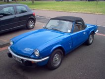
Over the last few months I've come to the inescapable conclusion that the time has come to properly restore my car! The last 7 years have taught me a lot about Triumph Spitfires - how they work, why they don't and, above all, the importance of top quality workmanship! Whenever I've had a job to do I've always tried to do it to the best of my abilities regardless of the time taken or, at times, the financial cost! The results of my labour is a car that is pretty much mechanically sorted. The bodywork however, is another kettle of fish. I've had a few patches welded on the floorpan in the past and needed a few more before the RBRR. This got me thinking - if I don't restore it soon it might deteriorate to the point where it's not worth doing.

I think that you basically seem to need a combination of four things to restore a car. Those four things are time, money, skills and space! When it comes to money and time, like everyone, I could do with more of both but I hope to keep the costs down by doing a lot of work myself. I also have the advantage that all the mechanical stuff is done already so I won't have the costs of that to factor in. In terms of skills, I'm going to need to learn how to MIG weld and I'm also going to have to get better at bodywork. There is really no getting away from that, those are essential! I've made a fairly serious investment along those lines but I'll discuss that another time!

In terms of space, I've really lucked out! My grandparents house is only a mile from my house and has a sizable double garage with a workshop at the back. It's full of junk but should be just fine once I've cleared it out. It has a special significance for me as well as I have many happy memories of the projects my grandad and I built in there before his death last year. Back in the 60's it was also used to build an Austin 7 special so I'm hoping it will bode well for my car! Here are a few pictures of my car settling in...


I've just started stripping it down. The front bumper, lights, spoiler, overiders and number plates are all removed and boxed up in my workshop. It begins...

Sunday, October 17, 2010

The Round Britain Reliability Run!

Better late than never! Here are some of my photos from the RBRR...


And that's it really! The car was flawless all the way around and we didn't have anything to do other than just drive. It was great fun and if you're thinking of doing it then go for it! It really is the ultimate test of man and machine!

Saturday, September 18, 2010

Headlight Relays

I wrote this blog entry a month or so ago but I was so busy preparing for the Round Britain Reliability Run I never got a chance to post it. So, finally, here it is...

I've had a couple of problems in the past few days with the dip / flash stalk on the steering column. My uprated Halogen headlamps seem to have been putting much more strain on the switchgear than the old sealed beam units. Last year I had to take the stalk off and repair it because the full beam terminal seemed to have heated up and melted into the nylon body of the stalk causing it to smoke and spark quite dramatically! After it failed again on the same dark country road as before I decided it was probably time to fit some headlight relays!

I'm not the greatest electrical engineer in the world so I decided to do my research first. After a bit of searching I found an excellent thread on the Club Triumph forum. Once I understood what I was doing I made up a circuit diagram.

Basically, instead of going direct to the lights the wires from the switchgear go to a relay instead. When the light switch is pressed the relay circuit activates the secondary circuit which connects the lights directly to the battery. So that's the theory! You also need to do a bit of maths to make sure the cable can support the current it needs to be carrying. All you really need to know is Power = Current x Voltage. Most headlamp bulbs are 55/60 Watt so the current will be around 5 amps. Because there are 2 headlamps we need cable and relays that can take at least 10 amps. I decided to go a bit bigger on the battery supply cable to give me more capacity for upgrades in the future. The relays required are the common as muck 30A type.

I first thought about where I was going to mount the relays themselves. It's easiest if they're up front with the rest of the wiring for the lights. On the CT forum, James mentioned that he'd seen the relays P clipped to the bonnet tubes. Initially I thought this would be a great idea but when I looked into it a bit more I discounted it on the grounds that the cables would eventually get weakened by the movement of repeatedly opening the bonnet. I decided on a custon bracket bolted behind the quater valance. I made this up out of 3mm alloy and test fitted it. Perfect! Now to start the wiring...


I started by fitting the brown relay supply cable. This attaches to the battery positive terminal with a ring terminal and goes straight to an inline fuse holder before joining the rest of the loom running to the front of the car.


At the front of the car I crimped it into a butt connector along with another two short lenghts to supply both of the relays. The brown wire attaches to the '30' terminal on the relay. On the picture below you can see a left over length of the brown wire is being used to temporarily hold the relays in place!


You can then start attaching the other wires. The low and high beam cables can be found by tracing the cabling from the headlamps to the connectors in the centre of the bonnet. There should be a number of 4-way connectors, each with 3 wires connected to it. The low beam is the blue wire with a pink trace. Remove the supply wire from the connector (the others go to the headlamps), shorten it, crimp a terminal and attach it to the relay. Now you just need to repeat that with the high beam wire (blue with white trace) and connect it to the other relay.


All you then need to do is connect up both the '87' terminals on each relay to the connectors by the headlamps. There we go - all done!

Wednesday, September 01, 2010

Electronic Ignition

I've been meaning to change to electronic ignition for ages. I was hoping to go straight to Megajolt but with the RBRR coming up fast I decided it was time to get something sorted! I've heard good things about the kits sold by 'SimonBBC' so I got one of eBay. BBC stands for 'Best British Classics' in case you're wondering and they have a website (http://www.simonbbc.com) as well as selling on eBay.

The kit contains a red module to put in the distributor, special rotor arm, a magnetic 'collar', grease, cable tie and various other bits. The fitting goes a little like this...

Firstly, you need to whip off the distributor cap to expose its innards. You no longer need the condenser or the points so they can both be removed by removing the two screws. You need to reuse the screws so keep them safe! There is also a braid connecting the baseplate to the distributor body. It doesn't say anything in the instructions about it but I removed it and it worked so I guess it either needs to be removed or makes no difference!


Once you've stripped the guts out you can install the ignition module. This needs to have the base coated in silicon grease before fitting. I think the reasoning behind this is to dissipate heat into the baseplate and prevent overheating. The module has a circle cut out of the bottom that matches up with a lump on the baseplate so the module 'locates' very easily. The instructions tell you to put the screws in loosely so you can adjust the proximity of the module to the collar on the distributor shaft. I actually found that with the locating bump and the two screws there wasn't really any potential for moving it and just did up the screws.


Now you need to fit the rotor arm and collar. The kit gives you a couple of different ways of doing this. Firstly, you can use the supplied rotor arm which comes with a collar built into the bottom to activate the ignition module or, secondly, you can fit a separate collar and use your own rotor arm. I'd just bought a new top quality 'red' rotor arm so I went with the latter option.


Then all you need to do it pass the wires out through the distributor body and connect the red one to the plus side of the coil and the black one to the negative. It's really important to leave enough free cable inside the distributor to allow the plate to advance and retard. I checked mine by sucking on the vacuum pipe! The cables in the kit were a little strange. One was too long and the other too short! I sorted this with a little spare cable and a few crimp connectors.

I then threw it all back together and reconnected the battery. It was time for a test drive! I turned the key and the engine span over but nothing happened. Something was wrong and it wouldn't fire. I suspected my connections at first but everything seemed to be in order when I tested them with my multimeter. There isn't much in this kit that can actually go wrong so my suspicions turned towards the stuff in the diff! I fitted the rotor arm with the built in collar just to see if that made any difference and it did! The engine fired up straight away. Comparing the position of the collar on the rotor arm with it built in and where I had it with my normal rotor arm revealed the problem. Basically, I'd just pushed the collar too far down the shaft for its motion to be picked up by the ignition module. All I did was refit the normal rotor arm and pull the collar up to the bottom of it. Job done!

I haven't driven the car since doing it but just at idle it sounds much smoother and I'm sure it's going to make a huge difference to how the engine feels. I'm really glad I did it and I can't believe I didn't do it sooner!